DIY Current meter using Arduino Circuit Diagram The multimeter is an indispensable tool for any electronics project, as it helps overcome countless challenges during project completion. This article will demonstrate how to create a cost-effective digital multimeter using an Arduino board and an OLED display. This multimeter is capable of measuring voltage, current, resistance, and capacitance.
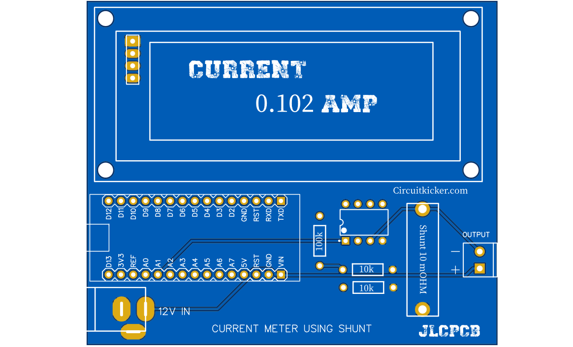
Design low resistance shunt resistor using a simple wire Display the dc current value on an LCD. it can be used as a digital Ammeter circuit for current measurement in electronics experiments. measure its resistance with the help of ohm meter. You can easily design .47 ohm resistor with the help of simple wire. It is a hit and trial method.
How to Measure Current in a Circuit: The Essential Guide Circuit Diagram
The transistors are BC640, however you may try other transistors like 8550 or 187 etc. The proposed digital voltmeter, ammeter circuit module can be effectively used with a power supply for indicating the voltage and current consumption by the connected load through the attached modules. Referring to the circuit diagram below, the 3 digit digital display module is build through the ICs CA 3162

The Micro Ampere Meter Circuit is a valuable tool for accurately measuring small electric currents typically in the microampere range. By using a combination of resistors, operational amplifiers and a current measuring device this circuit provides a reliable method for monitoring and analyzing low level currents in various electronic applications.

Build AC Power Meter Circuit Diagram
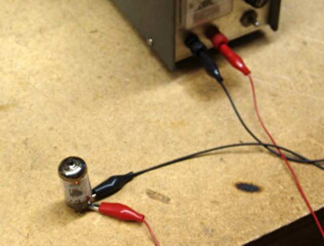
Step 3: After determining the full-scale current rating of your meter movement, you must accurately measure its internal resistance. To do this, disconnect all components from the previous testing circuit and connect your digital ohmmeter across the meter movement terminals. Record this resistance figure and the full-scale current figure
